

Views: 0 Author: Site Editor Publish Time: 2026-08-13 Origin: Site

In conventional fire alarm systems, the reliability of a manual activation device relies entirely on the integrity of its physical wiring and zone configuration. A single termination error can result in a zone fault or a failure to trigger during an emergency. Facility managers and fire safety integrators must ensure that newly installed or replacement devices interface correctly with legacy or new conventional panels. Installers must maintain precise resistance values for fault monitoring and alarm activation. This precision prevents system-wide short circuits. Integrators often face confusion regarding system compatibility, mistakenly attempting to wire commercial call points into domestic, panel-less smoke alarm circuits. This guide details the technical requirements, wiring topologies, and component evaluation criteria necessary to successfully integrate these devices into a conventional fire alarm zone, ensuring full compliance with commercial life safety standards.
Resistance-Based Activation: Conventional panels detect alarms and faults through changes in circuit resistance; correct installation requires precise integration of alarm resistors and End-of-Line (EOL) resistors.
Zone Limitations: Unlike addressable systems, a manual call point on a conventional panel triggers a general zone alarm. Strategic placement and clear zone mapping are critical for rapid incident location.
Component Selection: Choosing between a break glass unit and a resettable manual call point dictates long-term maintenance costs, while selecting single-action versus dual-action mechanisms impacts the rate of accidental false alarms.
Compliance & Testing: Proper termination, cable selection (e.g., fire-rated FP200), and adherence to regional standards (NFPA 72, BS 5839, or EN 54-11) are non-negotiable for system certification.
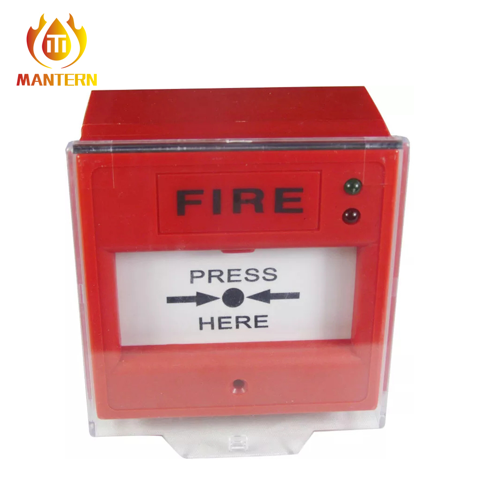
The primary goal is ensuring the fire panel accurately distinguishes between different electrical states. The panel must recognize a normal standby state. It must identify a wiring fault like an open or short circuit. Most importantly, it must detect a legitimate fire alarm activation. A properly wired device prevents ambiguous signals. Installers achieve this by strictly following manufacturer wiring schematics. Success means the panel reports faults immediately and triggers alarms instantly upon manual activation. You cannot leave room for intermittent faults caused by loose connections or incorrect resistor values.
Conventional systems use radial wiring circuits. Technicians often refer to these as spur circuits. The panel continuously monitors the electrical current running through these cables. A standard conventional zone operates on a 24-volt direct current loop. During normal operation, a small monitoring current flows through the circuit, regulated by the end-of-line resistor. When someone activates a Manual Call Point, it alters the electrical resistance of the circuit. This sudden drop in resistance increases the current flow significantly. The main control board detects this current spike. It then signals an alarm condition and activates the sounder circuits across the building.
Assigning devices to specific building zones requires careful spatial planning. Conventional zoning cannot pinpoint the exact device location. It only identifies the activated circuit loop. You must place each emergency alarm activation point strategically. Install them at fire exits, stairwells, and high-risk corridors. Building codes generally dictate that a person should not have to travel more than 30 to 45 meters to reach an activation point. Mount them at a height of 1.4 meters above the finished floor level for easy access. This strategic placement compensates for the lack of device-specific addressing. It speeds up incident response times for fire wardens. Clear zone charts must accompany the main control panel. These charts guide responders to the correct general area immediately.
Not all call points serve the same environmental or operational needs. Your component selection directly impacts upfront installation time. It also dictates ongoing maintenance requirements. Proper selection is the primary method for false alarm mitigation. You must match the device specifications to the building environment. Industrial floors require different hardware than office lobbies. Outdoor installations demand specific weatherproofing ratings, typically IP67, to prevent water ingress from corroding the internal microswitches.
The traditional break glass approach uses a frangible element. This fragile glass shatters when pressed by a user. It requires physical replacement of the glass post-activation. This style suits low-traffic areas perfectly. It acts as a strong deterrent against malicious activation because breaking glass requires deliberate force. Conversely, a resettable manual call point uses a flexible plastic element. The plastic element drops downwards upon pressing, simulating the break glass action without the mess. You can reset it immediately with a specialized plastic key. This makes it ideal for high-traffic areas, shopping centers, and schools. It is perfect for environments prone to accidental triggers where replacing glass constantly would be impractical.
Single-action devices require only one physical motion to activate. The user simply pushes the front element inward. Dual-action mechanisms feature protective transparent covers. The user must lift this hinged cover before pressing the element. We highly recommend dual-action units for gymnasiums, warehouses, and public corridors. They prevent accidental bumps from triggering building evacuations. Dual-action covers also deter casual vandalism in public spaces. They force the user to make a deliberate, two-step decision before sounding the alarm.
Industrial applications often require heavy-duty activation variants. You must check Normally Open (NO) versus Normally Closed (NC) contacts. These contacts must align with standard conventional panel requirements, which almost exclusively use Normally Open contacts that close upon activation. A standard fire alarm push button should feature local LED indicators. These small red LEDs illuminate steadily upon activation. They provide immediate visual confirmation to first responders. This local indication saves time before checking the main panel, allowing wardens to quickly identify exactly which unit on the zone was pressed.
Match the physical durability of the device to the facility. Consider the reset mechanism and protective housing carefully. Evaluate operational realities and vandalism risks before finalizing selection. Flush-mounted units look better in modern office environments, sitting flat against the plasterboard. Surface-mounted backboxes are easier to install on solid concrete or brick walls. Ensure the backbox provides adequate depth for cable management. Cramped backboxes often lead to pinched wires and earth faults when you screw the faceplate down.
Table: Comparison of Activation Mechanisms
Feature | Frangible Glass Unit | Flexible Plastic Unit | Dual-Action Cover |
|---|---|---|---|
Activation Method | Break glass | Push plastic element | Lift cover, push element |
Reset Process | Replace glass pane | Use specialized key | Use key, close cover |
False Alarm Risk | Moderate | High (if bumped) | Very Low |
Best Application | Secure areas, server rooms | Retail stores, offices | Schools, public halls, gyms |
Physical wiring requires strict adherence to technical requirements. You must wire the device correctly into the conventional zone circuit. Poor terminations are the leading cause of intermittent panel faults. Installers must use the correct tools for stripping and terminating. Rushing the physical installation compromises the entire life safety system. Every connection must be tight, secure, and electrically sound. A loose screw terminal will eventually cause an open circuit fault as building vibrations loosen the wire over time.
Use fire-resistant cabling for all life safety circuits. FP200 Gold or equivalent cables are strictly mandatory in most jurisdictions. These cables maintain circuit integrity during an actual fire, allowing the system to continue operating even when exposed to direct flames for a specified duration. You must also manage voltage drop across long cable runs. Ensure the wire gauge supports the total circuit length. Standard installations typically use 1.5mm squared solid copper cores. Route cables away from high-voltage electrical lines to prevent electromagnetic interference. Secure the cables with fire-rated metal clips or copper saddles, never plastic zip ties that will melt in a fire.
Identify the standard terminal blocks inside the device. These typically include Zone IN positive and Zone IN negative. They also include Zone OUT positive and Zone OUT negative. Maintain correct polarity throughout the entire zone circuit. Reversing polarity will cause false faults at the panel and prevent the device from triggering an alarm.
Strip the outer red or white cable insulation back by exactly 50 millimeters using a specialized stripping tool.
Carefully peel back the foil shield, ensuring you do not nick the inner red and black core insulation.
Sleeve the bare earth drain wire with green and yellow earth sleeving to prevent it from shorting against the circuit board.
Terminate the earth wire into the designated earth continuity block inside the backbox.
Strip 8 millimeters of insulation from the red and black cores.
Insert the red core into the positive terminal and the black core into the negative terminal, tightening the screws firmly.
Give each wire a gentle tug to ensure it is securely seated in the terminal block.
Pressing the element physically bridges the internal microswitch contacts. This mechanical action completes the electrical circuit loop. Conventional devices require an internal series alarm resistor. This resistor is typically 470 ohms or 680 ohms. The exact value depends on the panel manufacturer specifications. The resistor prevents a dead short across the panel terminals. Without this resistor, the panel registers a short circuit fault. It would fail to register a legitimate fire condition. Always verify the resistor value before mounting the device. Many modern units come with a selectable resistor, allowing you to choose between 470 and 680 ohms by moving a small jumper pin on the circuit board.
The EOL resistor is the most critical component for system integrity. It ensures the panel can detect breaks in the wiring. The panel measures the voltage drop across this specific resistor. If a cable breaks, the resistance becomes infinite. The panel immediately drops into an open circuit fault state and sounds a local buzzer. This continuous monitoring guarantees the circuit is always ready to transmit an alarm signal.
You must always place the EOL at the last device. It belongs at the physical end of the zone circuit. Never install the EOL resistor inside the panel itself. Placing the EOL at the panel defeats cable monitoring entirely. The panel would only monitor its own internal terminal blocks. It would remain blind to any severed cables in the building. This is a common and dangerous installation error made by inexperienced technicians trying to clear a fault quickly.
Terminate the EOL across the positive and negative terminals. Do this only at the final device on the loop. Calculate the correct EOL value based on panel specifications. Common EOL values include 4.7 kilo-ohms or 6.8 kilo-ohms. Secure the resistor legs firmly into the terminal block alongside the incoming zone cables. Ensure the bare metal legs do not touch each other or the metal backbox. A shorted EOL resistor will trigger a false fire alarm. Double-check the color bands on the resistor to confirm its value before installation.
Table: Common Resistor Values for Conventional Panels
Component | Typical Value Range | Function in Circuit | Location |
|---|---|---|---|
Alarm Series Resistor | 470Ω or 680Ω | Drops resistance to trigger alarm state | Inside every call point |
End-of-Line (EOL) Resistor | 4.7kΩ or 6.8kΩ | Maintains standby monitoring current | Only at the final device |
Detector Base Diode | Standard Rectifier Diode | Maintains continuity if detector is removed | Inside detector bases |
You must decide whether to wire manual devices on dedicated zones. Alternatively, you can mix them with automatic smoke and heat detectors. This decision impacts installation time, material costs, and future system scalability. Dedicated zones provide clearer information to emergency responders. Mixed zones save space on the physical control panel and reduce the total amount of cable required.
Mixing devices significantly reduces overall cabling requirements. It lowers the number of panel zones required for smaller installations. This approach suits compact retail spaces or single-floor offices perfectly. It requires less conduit and fewer fire-rated cable clips. Installers can run a single loop around the entire perimeter, picking up smoke detectors on the ceiling and call points by the doors. This unified approach simplifies the initial physical installation phase and reduces labor hours.
Mixed zones severely complicate incident response during an emergency. Responders cannot immediately know the exact source of the alarm. They will not know if a person triggered it manually after seeing a fire. They will not know if a detector sensed smoke automatically, which could just be burnt toast in a staff kitchen. This ambiguity delays critical decision-making during a building evacuation. Finding the source of a false alarm also takes much longer, as technicians must check every single device on that mixed zone.
Wiring a manual device in series with automatic detector bases requires care. You must maintain EOL integrity across all mixed devices. Ensure the alarm resistor values align with the detector base specifications. Some detector bases have integrated continuity diodes. These diodes allow call points to function even if a detector head is removed for maintenance. You must wire the call point into the correct base terminals. Incorrect wiring breaks the continuity of the entire mixed zone, causing the panel to show a fault until the wiring is corrected.
Identify and resolve common installation errors before system commissioning. Proactive testing prevents disruptive false alarms after building handover. Inspect every backbox for pinched wires or loose screws. Ensure all protective covers are securely fastened. Clean any construction dust out of the device housings. Plaster dust can interfere with the internal microswitch mechanisms, causing them to stick open or closed.
Open circuit faults happen frequently during new installations. They are caused by loose terminations, physically broken cables, or a missing EOL resistor. Short circuit faults occur due to damaged inner cable insulation, often caused by over-tightening cable glands. Installing a unit without the correct alarm series resistor also causes shorts. Earth faults happen when the cable shield touches a live terminal. They also occur if the bare drain wire touches a grounded metal backbox. Use a digital multimeter to isolate these wiring faults. Disconnect the zone from the panel and measure the resistance across the positive and negative legs to verify the EOL value.
Use the specialized test key to simulate a manual activation. This tests the system without breaking the frangible element. Verify the panel response times and zone LED indicators. Check the local device LEDs for proper red illumination. Document baseline resistance readings for future maintenance reference. Measure the total zone resistance with a multimeter. Record this value in the official fire system logbook. Regular testing ensures the mechanical parts do not seize over time and confirms the panel relays still activate the sounders.
Table: Troubleshooting Common Zone Faults
Panel Indication | Probable Cause | Diagnostic Step | Resolution |
|---|---|---|---|
Open Circuit Fault | Broken cable or missing EOL | Check voltage at last device | Repair cable or install EOL resistor |
Short Circuit Fault | Crushed cable or missing alarm resistor | Measure resistance across zone | Replace damaged cable section |
Earth Fault | Drain wire touching metal backbox | Test continuity to earth ground | Sleeve drain wire properly |
False Alarm | Water ingress or faulty microswitch | Inspect device for moisture | Replace unit with IP67 rated model |
Audit the existing zone wiring with a multimeter to determine the exact location and value of the current EOL resistor.
Select a compatible call point with the correct internal series resistor (470Ω or 680Ω) for your specific control panel brand.
Procure the necessary fire-rated FP200 cabling, secure appropriate surface or flush mounting backboxes, and gather proper termination tools.
Schedule the installation during a designated maintenance window to avoid disruptive false alarms for building occupants.
Test the newly installed device using the manufacturer-provided test key and log the results before final system sign-off.
A: Yes. Conventional panels require call points with specific internal series resistors, typically 470 ohms or 680 ohms. Addressable call points will not communicate with a conventional panel. Always verify the resistor value matches the panel manufacturer's specifications to ensure proper alarm activation instead of a short circuit fault.
A: A break glass unit uses a fragile glass element that shatters upon activation and requires physical replacement. A resettable unit uses a flexible plastic element that drops down when pushed. You can easily reset the plastic element using a specialized key, making it ideal for high-traffic areas.
A: No. Commercial manual call points are designed to interface with a central control panel that monitors circuit resistance. Domestic smoke alarms operate on different voltage and signaling protocols. Wiring a commercial call point into a domestic circuit will not function and violates fire safety codes.
A: A zone fault usually indicates an open circuit, a short circuit, or reversed polarity. Check that the End-of-Line (EOL) resistor is securely installed at the last device on the zone. Also, verify that the internal alarm resistor is present and that the positive and negative terminals are wired correctly.
A: The EOL resistor must always be installed across the terminals of the very last device on the zone circuit. Never install the EOL resistor inside the fire panel itself, as this completely disables the panel's ability to monitor the circuit cables for breaks or faults.
A: You must first place the fire panel into test mode or isolate the specific zone. Then, insert the manufacturer-provided test key into the bottom or side of the call point. This simulates an activation, dropping the element and triggering the local LED, without requiring you to break the glass.
Mantern Industrial Co., Ltd. is engaged in international business since 2012. Our aim is to provide good products with competitive price for our clients.
