

Views: 0 Author: Site Editor Publish Time: 2026-08-09 Origin: Site

Integrating life-safety devices into commercial or multi-tenant infrastructure requires exact electrical matching. A single mismatched component can compromise the entire life-safety network. Specifying the wrong voltage or relay configuration for a Wired CO Detector leads to control panel faults, false alarms, failed inspections, and costly rewiring. Facility managers and system designers must navigate competing standards to ensure seamless integration. To guarantee reliable operation and code compliance, evaluating the precise voltage inputs and relay output structures required by your specific Fire Alarm Control Panel (FACP) or Building Automation System (BAS) is a non-negotiable first step.
Voltage Matching is Absolute: System compatibility dictates whether a 12VDC, 24VDC, or 120VAC power supply is required, with 24VDC being the industry standard for commercial control panels.
Dual Relays are Critical for Diagnostics: Commercial-grade detectors require separate relays for "Alarm" (CO detection) and "Trouble" (sensor fault/loss of power/sensor expiration) to ensure accurate system monitoring.
Signaling Dictates Output Type: Simple interconnected systems rely on Form C dry contacts, while advanced BAS environments may require 4-20mA analog outputs for real-time concentration tracking.
Compliance Drives Selection: Detectors integrated into a building CO warning system must meet UL 2075 standards, which carry different electrical and signaling requirements than residential UL 2034 units.
Establishing the baseline requirements for a successful installation is critical. A reliable system demands continuous power, immediate fault reporting, and reliable alarm triggering without signal degradation. Life-safety infrastructure cannot tolerate intermittent communication. Every device on the network must perform its specific function flawlessly under both normal and emergency conditions. When you install these units on a job site, you quickly realize that theoretical wiring diagrams often clash with physical conduit runs and panel limitations.
Localized, self-contained units operate independently. They sound a local horn when gas is detected but do not notify central management. In contrast, system-connected detectors report directly to a central monitoring station. This architecture dictates the necessary electrical inputs and outputs. System-connected units require robust power inputs and dedicated communication pathways to relay status changes instantly. You will find that standalone units work fine for a small residential garage, but a commercial parking structure demands a fully integrated network.
Sending a binary signal to a fire panel differs vastly from sending variable data to a building automation system. Fire panels typically look for simple open or closed circuits to trigger evacuation protocols. A BAS often requires continuous data streams to modulate ventilation equipment based on specific gas concentrations. An effective building CO warning system ensures building-wide notification upon localized detection. This integration relies heavily on selecting the appropriate signaling hardware at the detector level. We often see contractors pull the wrong cable type because they misunderstood whether the device was talking to a fire panel or a BAS controller.
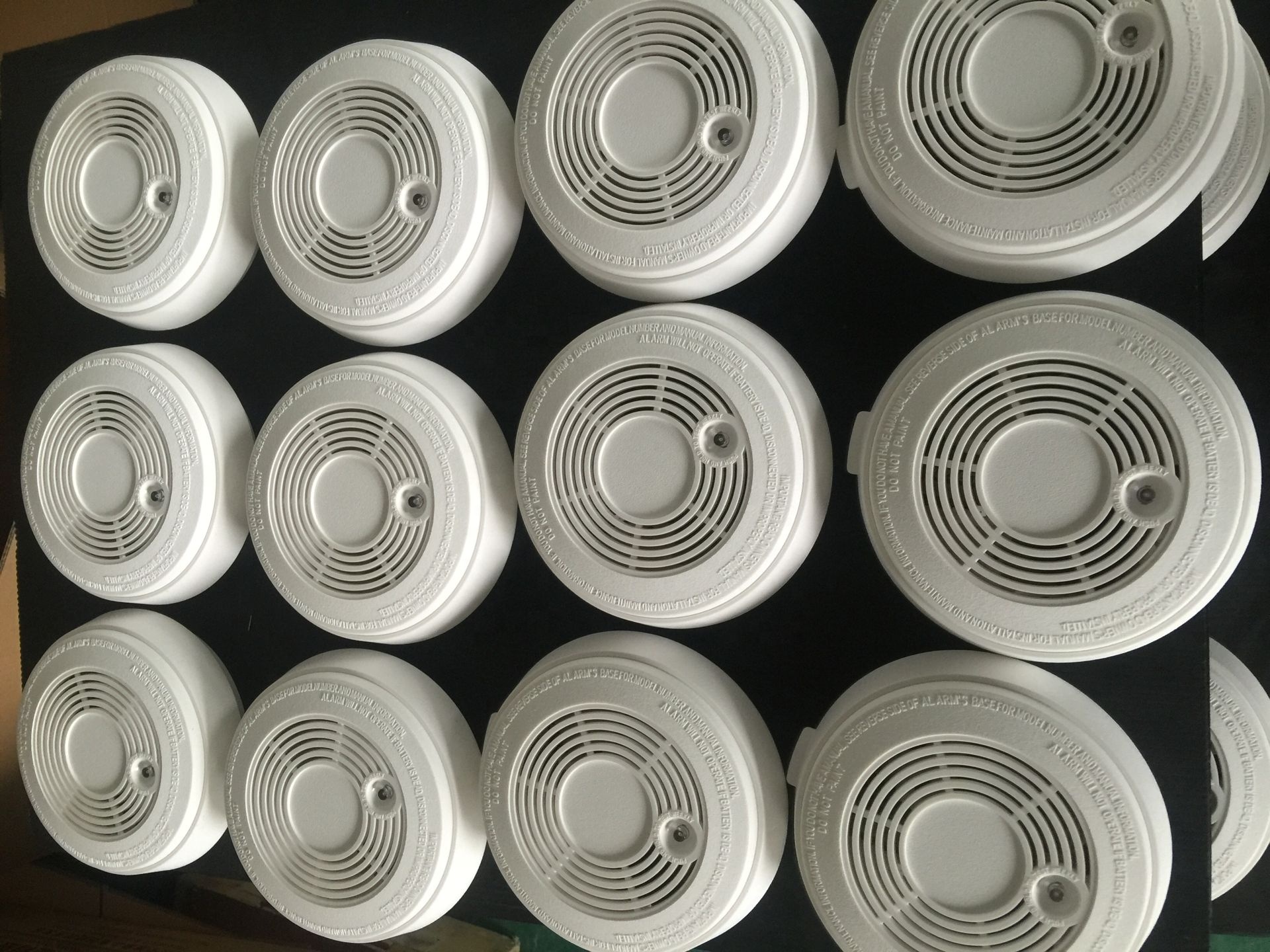
Matching the detector's operating voltage to the power supply is the most fundamental step in system design. Applying incorrect voltage will instantly destroy the sensor or cause erratic behavior. I have seen entire zones of detectors fried because an apprentice wired a 12VDC loop into a 24VDC auxiliary power block.
Commercial fire alarm and security panels predominantly utilize 24VDC power. This voltage standard allows for longer wire runs with acceptable voltage drop. Legacy security systems or specific marine applications often employ 12VDC circuits. Low-voltage systems offer safer maintenance procedures and integrate easily with centralized battery backups. Installers must verify whether the hardwired CO detector requires polarized connections. High ripple voltage from poorly filtered power supplies can cause erratic sensor readings or generate false trouble signals at the panel. Always check the power supply output with a multimeter before terminating the devices.
Residential or light commercial tandem systems frequently utilize 120VAC units. These detectors wire directly into the building's electrical grid. Attempting to integrate line-voltage units with low-voltage commercial FACPs presents significant limitations. 120VAC units typically lack the isolated dry contacts required by commercial fire panels. They are designed for localized alerting rather than facility-wide supervision. Pulling 120V wire also requires different conduit separation rules compared to low-voltage fire wire.
System designers must calculate the total current draw across a daisy-chained network. Every detector consumes power in both standby and alarm states. Exceeding the panel's auxiliary power supply capacity leads to system failure during an emergency. National Fire Protection Association (NFPA) 72 mandates specific secondary power requirements. Centralized panel batteries provide supervised, reliable backup power for all connected low-voltage devices. This approach is far superior to relying on localized 9V or AA batteries, which require constant manual replacement and offer no central supervision.
Voltage Type | Typical Application | Wiring Requirement | Backup Power Source |
|---|---|---|---|
12VDC | Legacy Security, Marine, RV | 18-14 AWG Low Voltage | Central Panel Battery |
24VDC | Commercial Fire Alarm Panels | 18-14 AWG Fire Wire (FPL/FPLR) | Central Panel Battery |
120VAC | Residential, Small Commercial | 14-12 AWG Romex/THHN | Local 9V/AA Battery |
The method a detector uses to communicate with the control panel determines the system's overall capabilities. Relay outputs translate physical gas detection into electrical signals the panel understands. You need to know exactly what the panel expects to see when a zone goes into alarm.
Form C relays act as Single Pole Double Throw (SPDT) switches. They create a closed or open circuit upon alarm activation. Installers can choose between Normally Open (NO) and Normally Closed (NC) configurations. Fail-safe supervisory circuits almost exclusively use NC wiring. If a wire breaks or power is lost, the NC circuit opens, immediately alerting the panel to a fault condition. Wiring NO circuits for fire alarm initiation is generally frowned upon because a severed wire will never report a fault.
Onboard relays possess strict electrical limits. Typical ratings hover around 1A at 30VDC or 0.5A at 125VAC. Direct-wiring inductive loads to these relays is a critical error. Heavy ventilation fans or motorized dampers generate massive inrush currents upon startup. This current will weld the small relay contacts together, destroying the detector. You must use an external interposing isolation relay to switch heavy mechanical loads safely. I have replaced dozens of detectors where the internal relay was completely fused because someone tried to switch a 5-amp exhaust fan directly.
Commercial environments require a clear distinction between an "Alarm" state and a "Trouble" state. An alarm indicates hazardous gas levels requiring evacuation. A trouble state signals sensor end-of-life, a removed cover, or a power failure. A commercial unit must feature independent relays for these conditions. Triggering a full building evacuation because a single sensor reached its expiration date is unacceptable. The trouble relay handles physical sensor degradation and transmits the end-of-life warning signal after the unit's operational span concludes.
Industrial applications and enclosed parking garages often utilize 4-20mA analog outputs. These signals provide continuous, real-time gas concentration data. Analog signals allow a BAS to execute tiered responses. The system might activate low-speed exhaust fans at 25 ppm. If concentrations reach 70 ppm, the system can trigger high-speed ventilation and initiate localized alarms. This granular control is impossible with simple binary relays. Running shielded cable is usually necessary for 4-20mA loops to prevent electromagnetic interference from skewing the analog readings.
The physical wiring layout dictates how devices communicate and how resilient the network is against physical damage. Planning the conduit runs and wire paths before pulling cable saves days of troubleshooting later.
Connecting multiple detectors in tandem involves specific physical wiring limitations. Voltage drop and signal degradation restrict the maximum number of units on a single circuit. Exceeding these limits causes downstream devices to fail or communicate unreliably. Installers must consult manufacturer specifications to determine the exact device limit for a specific wire gauge and run length. A common mistake is putting 30 devices on a single 18 AWG run and wondering why the last five units keep dropping offline.
Fire alarm circuits typically utilize Class A or Class B wiring schemes. Class B loops require a single End-of-Line (EOL) resistor at the furthest device. The circuit does not return to the panel. A single wire break on a Class B loop severs communication with all downstream devices. Class A loops provide a redundant path back to the control panel. If a wire breaks, the panel feeds power and data from both directions, maintaining full communication with every interconnected carbon monoxide alarm on the loop. Class A requires more wire and conduit space but offers superior reliability.
Conventional relay-based zoning provides limited diagnostic information. The panel only knows which zone is in alarm, not the specific device. Addressable systems assign a unique digital ID to each detector. The panel identifies the exact location of the alarm or trouble condition instantly. Addressable units require specific communication modules or utilize proprietary protocols to interface with the main control panel. When troubleshooting a ground fault on a conventional system, you have to split the circuit manually. With an addressable system, the panel tells you exactly where to look.
Selecting hardware based solely on electrical specifications ignores the critical regulatory landscape governing life-safety systems. Code compliance is just as important as electrical functionality.
Understanding Underwriters Laboratories (UL) standards prevents costly inspection failures. UL 2034 applies to single or multiple station alarms, typically found in residential applications. UL 2075 governs gas and vapor detectors connected directly to commercial control panels. Specifying a UL 2034 device for a commercial fire panel integration will result in a failed fire marshal inspection. The electrical and signaling requirements differ significantly between the two standards.
Feature | UL 2034 (Residential/Tandem) | UL 2075 (Commercial/Panel-Connected) |
|---|---|---|
Primary Application | Homes, apartments, localized alerting | Commercial buildings, FACP integration |
Typical Voltage | 120VAC or standalone battery | 12VDC or 24VDC from control panel |
Signaling Method | Local horn, simple tandem interconnect | Form C relays, addressable modules |
Supervision | Minimal (local chirp for low battery) | Continuous panel supervision (Alarm/Trouble) |
Local jurisdictions enforce installation rules under current building codes. NFPA 72 and NFPA 720 mandate specific mounting locations. Detectors must be placed appropriately on walls or ceilings based on airflow and manufacturer guidelines. These standards also dictate strict testing intervals and maintenance schedules to ensure continuous operational readiness. You cannot just mount a detector wherever it is convenient for the conduit run; it must be placed where gas will actually accumulate.
Long wire runs introduce significant electrical resistance. This resistance causes the voltage to drop below the detector's minimum operating threshold. Devices at the end of a long run may fail to operate during an alarm condition. Mitigation strategies include utilizing thicker gauge wire, such as 14 AWG instead of 18 AWG. Installing auxiliary power supplies closer to the devices also resolves severe voltage drop issues. Always run the voltage drop math before ordering your wire spools.
EOL resistors supervise the integrity of the wiring loop. They allow a small trickle current to flow, proving the wires are intact. Incorrect EOL resistor placement masks critical wiring faults. Installing the resistor at the panel instead of the last physical detector defeats the supervision entirely. The panel will read the circuit as normal even if the wires to the detectors are completely severed. I have failed many contractor installations because they left the EOL resistor screwed into the panel terminals.
Verify the control panel's auxiliary power output to confirm whether 12VDC or 24VDC is required before purchasing devices.
Determine the required signaling method based on your system architecture, choosing between dry contacts or analog outputs.
Ensure the selected unit features dual relays for distinct alarm and trouble reporting to prevent false evacuations.
Confirm the device carries a UL 2075 listing for commercial panel integration to pass fire marshal inspections.
Calculate voltage drop for all long wire runs and upsize the wire gauge if necessary to maintain minimum operating voltage.
A: Direct connection is incompatible. 120VAC units typically lack the necessary isolated dry contacts required for low-voltage panel integration. Furthermore, they rarely carry the UL 2075 listing mandated for devices connected to commercial 24VDC fire alarm control panels.
A: The alarm relay activates only when the sensor detects hazardous gas levels, initiating emergency protocols. The trouble relay signals device-level faults, such as power loss, physical tampering, or sensor expiration, alerting maintenance personnel without triggering a full evacuation.
A: Conventional 120VAC tandem systems usually cap at 12 to 18 devices due to signaling limitations. However, 24VDC panel-connected systems are limited only by the control panel's auxiliary power supply capacity and the maximum addressable zone count.
A: No. A 4-20mA output is generally reserved for advanced BAS integration or industrial ventilation control where variable data is needed. Standard fire alarm panels only require binary Form C dry contacts to register simple alarm or trouble states.
A: Standard installations typically use 18 AWG to 14 AWG wire. The exact gauge depends entirely on the total length of the wire run and the combined current draw of all daisy-chained devices to prevent unacceptable voltage drop.
A: No. The small onboard relays of a wired CO detector cannot handle the massive inductive inrush current generated by a fan motor. Direct wiring will destroy the detector. An external interposing isolation relay is mandatory for switching heavy mechanical loads.
Mantern Industrial Co., Ltd. is engaged in international business since 2012. Our aim is to provide good products with competitive price for our clients.
