

Views: 0 Author: Site Editor Publish Time: 2026-08-08 Origin: Site

A standalone gas detection unit provides localized warning, but mitigating a catastrophic leak requires automated mechanical intervention driven by precise, rapid-acting relay outputs. When combustible gas concentrations reach dangerous levels, relying solely on audible alerts leaves facilities vulnerable. You need automated systems to shut off fuel lines, activate exhaust fans, and notify central monitoring stations instantly.
Specifying a detector with incorrect relay configurations results in failed integrations with shut-off valves, exhaust systems, or Building Management Systems. Mismatched voltage ratings, insufficient poles, lacking supervision, or incorrect latching logic can lead to code violations, property damage, and severe safety vulnerabilities. Engineers and facility managers must select the exact electrical interface required to drive these critical safety mechanisms.
This guide provides a technical framework for evaluating and selecting the correct relay outputs for natural gas detection systems. You will learn how to match relay specifications to mechanical loads, configure fail-safe logic, ensure seamless integration with facility infrastructure, and maintain strict compliance with life safety codes.
Relay Configuration Dictates Functionality: Single Pole Double Throw (SPDT) relays are standard for simple alerts, while Double Pole Double Throw (DPDT) or multiple discrete relays are required for simultaneous, multi-system automated responses.
Contact Ratings Matter: Relay contacts must be rated for the specific electrical load of the connected device; inductive loads (like exhaust fan motors and solenoids) require different protection and specifications than resistive loads or low-voltage fire panels.
Fail-Safe Logic is Mandatory: Selecting between Normally Open (NO) and Normally Closed (NC) states, alongside energized/de-energized states, determines whether a system defaults to a safe condition during a power failure or wire break.
Application Drives the Spec: A kitchen natural gas detector requires different relay logic (e.g., immediate solenoid shut-off and shunt-trip activation) compared to an industrial boiler room detector tied to a facility-wide SCADA system.
Compliance is Non-Negotiable: Specifying relay outputs must align with current standards, specifically NFPA 715 (Fuel Gas Detection), UL 2075, and UL 1484.
Relays serve as the critical electrical bridge between a localized methane leak alarm and facility-wide mechanical mitigation. Understanding the fundamental interface types ensures proper system architecture. When a sensor detects a hazardous accumulation of combustible gas, the internal circuitry must translate that chemical detection into a physical electrical change. This is where the relay comes into play, acting as an electrically operated switch that controls a separate, often higher-power circuit.
Gas detection architectures utilize either dry contacts or wet outputs. Dry contacts act as simple mechanical switches. They do not supply power to the connected circuit. Instead, they open or close a circuit powered by an external source, such as a fire alarm control panel or a dedicated power supply for a solenoid valve. Wet outputs, on the other hand, supply voltage directly from the detector to the connected device. Dry contacts offer superior flexibility, allowing you to integrate the detector across varying voltage domains without risking electrical cross-contamination.
Interface Type | Power Source | Primary Advantage | Common Application |
|---|---|---|---|
Dry Contact | External (Provided by connected system) | High flexibility, isolates voltage domains | Fire Alarm Control Panels (FACP), BMS integration |
Wet Output | Internal (Provided by the detector) | Simplified wiring for low-draw devices | Directly driving local strobes or small horns |
When a sensor detects combustible gas, the internal microprocessor evaluates the concentration against programmed thresholds. Once the threshold is breached, the processor energizes or de-energizes the relay coil. The magnetic field moves the internal armature, changing the state of the contacts. This physical movement completes or breaks the external circuit, translating a chemical detection event into immediate mechanical action. The speed and reliability of this mechanical action are paramount for life safety.
Establishing baseline requirements before procurement prevents integration failures. You must evaluate response time, load capacity, circuit supervision, and integration compatibility. The relay must handle the inrush current of the connected device. It must actuate within milliseconds of the alarm state. Furthermore, the circuit should support end-of-line resistors for continuous supervision, ensuring wiring integrity remains intact. If a wire breaks or a terminal comes loose, the supervising system must register a fault immediately.
Transient gas spikes from cooking vapors or harmless industrial processes often cause nuisance trips. You can mitigate these false alarms using adjustable relay activation delay times. Programming a 10 to 60-second delay allows temporary gas concentrations to dissipate before the relay triggers a massive mechanical response, preventing unnecessary facility shutdowns while maintaining core safety parameters. This delay must be carefully calculated based on the volume of the space and the potential flow rate of a genuine leak.
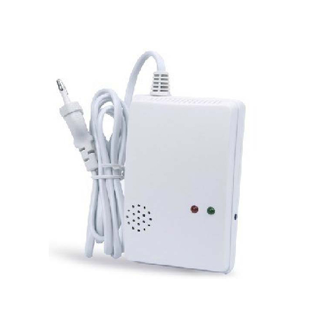
Selecting the right relay type dictates how many external devices the detector can control simultaneously and how much electrical load it can safely manage. A mismatch here leads to burned-out contacts, failed actuations, and compromised safety protocols.
Single Pole Double Throw (SPDT) relays feature one common terminal, one normally open terminal, and one normally closed terminal. They excel at single-action triggers, such as sending a fault signal to a control panel. However, SPDT relays face limitations in complex environments requiring multiple isolated actions. If you need to shut down a gas valve and simultaneously send a signal to a 24VDC fire panel, a single SPDT relay cannot handle both without mixing voltages.
Double Pole Double Throw (DPDT) relays provide two completely isolated SPDT switches operated by a single coil. This configuration offers distinct advantages for dual-action responses. You can simultaneously trigger a local 24VDC horn and shut off a 120VAC gas valve without crossing voltage domains. Multiple discrete relays allow separate, programmable responses for Low Alarm, High Alarm, and System Faults, providing granular control over the mitigation strategy.
Identify the number of distinct mechanical actions required upon alarm.
Determine the voltage and current requirements for each action.
Select a detector with enough isolated poles (SPDT vs DPDT) to handle the actions without mixing incompatible power sources.
Verify that the detector offers separate relays for fault conditions versus alarm conditions.
Relay contacts must match the electrical demands of the connected load. Low-voltage signaling interfaces with 12VDC or 24VDC fire alarm control panels or direct digital controllers. These applications typically require gold-plated contacts. Standard silver contacts can develop oxidation layers that low voltages cannot punch through, leading to signal failure. Line-voltage switching requires robust contacts capable of directly switching 120VAC or 240VAC loads without overheating.
Understanding inductive versus resistive loads prevents premature relay failure. Directly wiring a relay to a heavy inductive load, like an exhaust fan, without a motor starter causes contact welding. When the relay opens an inductive circuit, the collapsing magnetic field generates a massive voltage spike. This spike arcs across the opening contacts, melting the metal and fusing them together. Integrating RC snubbers for AC circuits or flyback diodes for DC circuits provides necessary arc suppression protection, absorbing the inductive spike and extending relay life.
Normally Open (NO) configurations keep the circuit broken during standard operation. The relay closes the circuit only upon gas detection. This represents the standard configuration for triggering external auxiliary alarms or exhaust fans. Normally Closed (NC) states maintain a completed circuit during normal operation. The relay opens the circuit during an alarm. NC configurations establish the standard for fail-safe operations. A "de-energized on alarm" configuration ensures that a severed wire or complete loss of detector power automatically drops power to a normally closed gas solenoid valve, defaulting the system to a safe condition.
Non-latching relays automatically revert to their normal state once gas levels drop below the alarm threshold. They work best for automatic ventilation control and signaling temporary alerts. Latching relays maintain their alarm state until physically reset by a technician. This manual reset function is mandatory for fuel shut-off applications. It prevents automated gas restoration before a qualified professional investigates and repairs the leak. When evaluating latching relays, investigate power-cycle resets. A power outage should not bypass the latching state; the relay must remember its alarm condition when power returns.
Different environments demand specific relay logic and integration strategies to effectively mitigate gas hazards. You cannot apply a one-size-fits-all approach to relay configuration.
Commercial kitchens, boiler rooms, and laboratories require immediate fuel isolation during a leak. This application requires a dedicated, latching relay wired to a normally closed gas solenoid valve. When evaluating a kitchen natural gas detector, verify compatibility with existing hood suppression system micro-switches and emergency pull stations. You often need a secondary relay contact to actuate a shunt-trip circuit breaker. This cuts electrical power to appliances under the hood, eliminating potential ignition sources simultaneously with the gas shut-off.
Enclosed parking garages, battery rooms, and industrial processing areas rely on rapid ventilation to clear hazardous gases. These spaces require non-latching relays triggered at a low-level alarm threshold, typically 10% of the Lower Explosive Limit (LEL). Activating fans early dissipates gas before it reaches critical levels. Always use the detector's relay to pilot a heavy-duty motor contactor. Never carry the fan's full run-load directly through the detector's internal relay, as the inrush current will destroy the contacts.
Commercial buildings require centralized life safety monitoring. FACP integration demands dry contacts wired to a monitor module on the Addressable Signaling Line Circuit (SLC) loop. You must utilize End-of-Line (EOL) resistors across the relay contacts to monitor wiring integrity for open or short circuits. Distinguish between supervisory signals for low-level leaks and alarm signals for high-level gas concentrations by utilizing dual relay outputs, allowing the central station to dispatch the appropriate response.
Large-scale industrial or institutional facilities integrate gas detection into comprehensive management platforms. Fault relays and alarm relays operate in conjunction with analog 4-20mA or digital Modbus communication outputs. Implement redundancy planning by using hardwired relays for local safety-critical actions, like closing valves and starting fans, while reserving digital outputs for remote data logging, trending, and system monitoring.
The physical installation environment directly influences relay wiring strategies and enclosure requirements. Proper placement and housing ensure the relays function reliably over the lifespan of the detector.
Methane is lighter than air, dictating high placement for sensors. The physical location of a wall mounted gas alarm—typically within 12 inches of the ceiling—impacts relay wiring runs and conduit routing. You must evaluate the internal space of the detector housing. The enclosure must provide sufficient room for terminating multiple field relay connections safely, maintaining proper separation between low-voltage signaling wires and line-voltage switching wires to prevent electromagnetic interference.
Environmental hazards dictate enclosure specifications. Ensure the detector's NEMA or IP rating protects the internal relay contacts from moisture, washdown environments, dust, and corrosive gases. In hazardous locations, relays must reside within Class I, Division 1 or Division 2 certified explosion-proof enclosures. These robust housings prevent the relay's internal electrical arc from igniting ambient combustible gas during actuation.
Failing to account for electrical limitations and code requirements compromises the entire safety system. Regulatory compliance is not just about passing inspections; it is about ensuring the system performs flawlessly during a catastrophic event.
Long wire runs between the detector relay and the actuated device present a significant risk. Voltage drop across extended distances can cause a main gas valve to fail to actuate or hold its position. Calculate wire gauge requirements based on the specific current draw of the connected load. For extreme distances, utilize interposing relays near the actuated device to handle the heavy load, using the detector's relay merely for low-current signaling.
Designing a system where a power failure at the detector leaves the facility vulnerable to an undetected leak violates core safety principles. You must mandate "energized to operate" versus "de-energized to operate" logic based on the specific mechanical mitigation strategy. Fuel shut-off valves should always drop closed upon loss of power, ensuring a fail-safe posture. If the wire is cut, the valve closes. If the power fails, the valve closes.
Improper relay sequencing, lack of supervision, or missing manual reset capabilities on fuel shut-offs will result in failed fire marshal inspections. Align all relay specifications with NFPA 715 for Fuel Gas Detection, NFPA 54 for National Fuel Gas Code, and NFPA 72 for National Fire Alarm and Signaling Code requirements. Confirm the Natural Gas Detector holds proper certifications, such as UL 1484 for commercial kitchens or UL 2075 for system-connected devices, ensuring strict regulatory compliance.
Selecting the correct relay outputs ensures your gas detection system can effectively drive mechanical mitigation strategies. Take the following steps to secure your facility:
Audit all connected mechanical loads to determine exact voltage, amperage, and inductive protection requirements for your relays.
Implement latching, normally closed relays for all fuel shut-off applications to guarantee fail-safe operation and mandate manual resets.
Verify that your selected detector provides adequate physical space and terminal separation for safe, interference-free field wiring.
Consult local fire codes and NFPA standards to ensure your relay logic and supervision methods meet all regulatory compliance mandates.
A: A dry contact acts as a simple mechanical switch that does not provide power, requiring an external power source for the connected circuit. A wet contact supplies voltage directly from the detector's internal power supply to drive the connected device.
A: Latching relays maintain their triggered state even if gas levels drop. This prevents the system from automatically restoring fuel flow before a technician physically inspects the area, repairs the leak, and manually resets the system.
A: No. Exhaust fans are heavy inductive loads that draw significant inrush current. Wiring them directly will cause contact welding and destroy the relay. Always use the detector's relay to trigger a heavy-duty motor contactor.
A: Fail-safe logic ensures that if the system loses power or a wire breaks, the connected safety device defaults to a secure state. For example, a normally closed gas valve will automatically shut off fuel flow if the relay loses power.
A: Utilize the detector's programmable relay activation delay. Setting a short delay allows transient, harmless gas spikes from cooking or industrial processes to dissipate before the relay actuates mechanical responses.
A: An EOL resistor allows a fire alarm control panel to continuously monitor the integrity of the wiring connected to the relay. It ensures the panel can detect open circuits or shorts before an actual emergency occurs.
Mantern Industrial Co., Ltd. is engaged in international business since 2012. Our aim is to provide good products with competitive price for our clients.
