

Views: 0 Author: Site Editor Publish Time: 2026-08-11 Origin: Site

A gas detection system is only as effective as its ability to initiate a physical safety response. Without the correct relay logic, detecting a hazardous gas leak does not translate into mitigating it. Facility managers and safety engineers frequently under-specify relay requirements. This oversight leads to incompatible voltage ratings, relay chatter, or the inability to drive external devices like solenoid valves, exhaust fans, or remote annunciators. Selecting the right Gas Controller requires a rigorous evaluation of relay types, fail-safe configurations, and zone logic. You must ensure code-compliant, reliable actuation during a gas event. We will break down exactly how to match your controller's outputs to your facility's mechanical infrastructure.
Relay Type Dictates Capability: Understanding the difference between Form A (SPST) and Form C (SPDT/DPDT) relays is critical for matching the controller to the required external load.
Fail-Safe Logic is Non-Negotiable: Life-safety applications require normally energized relays to ensure system faults or power losses trigger a safe state.
Load Ratings Matter: Exceeding the amperage or voltage limits of a relay output gas controller—particularly with inductive loads like motors—will cause premature relay failure.
Scalability Requires Advanced Logic: Multi-point detection systems rely on voting logic and zone-based relay assignments to prevent localized leaks from triggering facility-wide shutdowns.
The primary objective of a controller's relays is straightforward. They translate low-voltage sensor signals into actionable, high-voltage mechanical responses. A standard gas sensor outputs a low-power signal. This is typically a 4-20mA analog loop or a digital Modbus RS-485 string. This weak signal cannot directly power a heavy industrial fan. It cannot close a large mechanical valve. The relay acts as the vital bridge between delicate printed circuit boards and heavy mechanical infrastructure.
The sequence of operations follows a strict path. First, the sensor detects ambient gas concentrations. Next, the gas alarm controller processes this signal against predefined alarm thresholds. Once a threshold is breached, the controller commands the relay coil to change state. Finally, the relay contacts open or close, completing or breaking the external circuit.
Relays drive a wide variety of standard safety devices. Common actuation targets include:
HVAC dampers to seal off contaminated zones and prevent gas migration.
Emergency exhaust fans to ventilate accumulated combustible or toxic gases.
Solenoid valves to shut off the primary gas supply line at the source.
Remote strobe lights and audible horns for immediate personnel evacuation.
Shunt trips to disconnect power from potential ignition sources in classified areas.
Auto-dialers to notify off-site emergency response teams.
Relay applications shift dramatically depending on the operating environment. In a commercial boiler room, a simple carbon monoxide detection setup might only need to drive a single solenoid valve and a local horn. You wire the relay to drop power to the valve, shutting off the fuel supply.
Conversely, upstream oil and gas facilities require complex emergency shutdown sequences. A single hydrogen sulfide leak might need to trigger visual alarms, shut down process pumps, and activate flare systems simultaneously. A successfully specified controller must actuate the correct device at the exact required moment. It must do so without false trips or electrical failure. We see this often in the field when installers assume all relays are created equal. They wire a 10-amp motor directly to a 5-amp board relay, and the contacts weld shut on the first test.
Understanding physical relay configurations is essential when specifying a relay output gas controller. Commercial and industrial controllers offer various relay types. Each suits specific switching tasks.
The most common distinction lies between Form A and Form C relays. Form A relays, also known as Single Pole Single Throw (SPST), provide a simple on/off function. They feature normally open contacts. When the alarm triggers, the contacts close to complete a circuit. Engineers typically use Form A relays for basic signaling. You might use one to trip a conventional fire alarm panel zone.
Form C relays, or Single Pole Double Throw (SPDT), offer far more versatility. They feature three terminals: Common, Normally Open (NO), and Normally Closed (NC). This configuration allows the controller to toggle power between two distinct states. For example, a Form C relay can simultaneously cut power to a process machine while routing power to an emergency exhaust fan. This dual-action capability makes Form C the standard for robust safety systems. You bring your line voltage into the Common terminal. You wire the fan to the NO terminal and the process machine to the NC terminal. When the relay trips, the machine dies, and the fan spins up. Form C relays are the workhorses of the industry. Because they have both NO and NC contacts, they inherently prevent conflicting commands. You cannot accidentally send a run and stop command to the same device simultaneously because the physical switch can only be in one position at a time.
Advanced switching needs often require Double Pole Single Throw (DPST) or Double Pole Double Throw (DPDT) configurations. These relays contain two separate switches operating in tandem. A single coil drives both. They are mandatory for isolating distinct voltage circuits. A DPDT relay can switch a 24VDC local alarm circuit and a 120VAC ventilation fan simultaneously during a single gas event. This isolation prevents dangerous cross-wiring between high and low-voltage systems. If you mix 120VAC and 24VDC on a single pole, a short circuit will destroy your entire low-voltage control network.
You must also differentiate between dry contacts and wet contacts. Dry contacts act merely as a switch. They do not supply power to the load. You must provide an external power source through the relay contacts to drive the device. Wet contacts, or powered relays, supply line voltage directly from the controller's power supply to the load. Dry contacts offer superior flexibility and circuit isolation. Wet contacts simplify wiring for low-power devices like local piezos or small LED indicators. In heavy industrial applications, we almost exclusively use dry contacts to pilot external power sources.
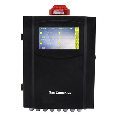
Physical hardware is only half the equation. The software-side logic dictating how the controller manages those relays determines the system's reliability. Engineers must configure this logic to match the specific hazards of the facility. You cannot rely on factory default settings for life-safety applications.
The most critical configuration choice is between fail-safe and non-fail-safe logic. In a fail-safe setup, the relay is normally energized. The controller supplies constant power to the relay coil during normal, safe operation. If the controller loses power, or if a wire is severed, the coil loses power. The relay drops its state, immediately triggering the external alarm or safety actuation. This configuration is mandatory for critical life-safety systems. It ensures that a dead controller results in a safe, alarmed state rather than silent failure. If a forklift clips your conduit and severs the communication line, the system fails safe. The exhaust fans turn on, and the gas valves shut off.
Non-fail-safe logic operates in reverse. The relay remains normally de-energized. It only receives power when the controller detects an alarm state. This approach is inherently riskier. If the facility loses power, or the controller's power supply fails, the relay cannot actuate. The system remains silent during a potentially catastrophic event. We only use non-fail-safe logic for non-critical monitoring or secondary notification circuits.
Another crucial setting is latching versus non-latching alarms. Non-latching relays automatically reset once the ambient gas concentration drops below the alarm threshold. This works well for minor ventilation control. If carbon monoxide builds up in a parking garage, the fans kick on. Once the air clears, the fans turn off.
Latching relays remain active even after the gas clears. They require a human operator to physically acknowledge the event and manually reset the controller. Latching logic is essential for severe hazards. If you have a combustible gas leak in a chemical plant, you want the system to stay in alarm until a technician investigates the root cause. You do not want the system auto-resetting and allowing operators back into a potentially compromised area.
Time delays and hysteresis settings prevent mechanical wear. If a gas concentration hovers exactly at the alarm setpoint, the relay might rapidly switch on and off. This phenomenon, known as relay chatter, destroys relay contacts and burns out external motors. Programming an ON delay requires the gas level to remain above the threshold for a set time before actuating. This filters out transient gas puffs. Hysteresis creates a deadband. If your alarm triggers at 50 ppm, a hysteresis setting of 10 ppm ensures the relay does not reset until the gas level drops below 40 ppm. This prevents the relay from bouncing if the reading fluctuates between 49 and 51 ppm.
Complex industrial environments require multiple sensors and tiered safety responses. A single-zone approach is rarely sufficient for large facilities. Scaling actuation requires a robust multi channel gas panel capable of advanced logic mapping.
Facility managers must evaluate the trade-offs between zone control and global actuation. Global actuation is simple: any sensor detecting gas triggers all facility relays. This causes facility-wide shutdowns and mass evacuations. While safe, it causes massive operational disruption for localized leaks. If a small ammonia leak occurs in one compressor room, you do not need to shut down the entire refrigeration plant.
Zone control solves this by mapping specific sensors to specific relays. If Sensor A in the battery room detects hydrogen, the controller only activates the exhaust fan in the battery room. The rest of the facility remains operational. You program the controller to group sensors logically based on physical room boundaries or HVAC zones. In a large parking garage, you might have 50 carbon monoxide sensors. You do not want all exhaust fans turning on if one sensor detects a localized vehicle exhaust plume. You group the sensors into zones corresponding to the physical ventilation shafts. Zone 1 sensors trigger Zone 1 fans. This saves massive amounts of electricity and reduces wear on the mechanical equipment.
Advanced systems rely heavily on voting logic, also known as cross-zoning. Voting logic requires multiple sensors to confirm a gas event before actuating critical relays. Common configurations include 1oo2 (one out of two) or 2oo3 (two out of three). In a 2oo3 setup, a single sensor hitting an alarm threshold might trigger a localized warning strobe. However, the controller will not shut down the primary gas supply valve until a second sensor in the same zone also hits the threshold.
Voting logic drastically reduces costly false alarms caused by sensor drift, water ingress, or temporary environmental anomalies. If a worker sprays a solvent near a single sensor, it might spike. Voting logic prevents that single spike from dumping the entire process line.
As facilities grow, base controllers often lack sufficient onboard relays to handle the required number of outputs. A standard panel might only have three or four relays. Expanding relay capacity requires modular architecture. Engineers can install expansion modules directly inside the main controller enclosure.
Alternatively, they can deploy remote relay nodes connected via RS-485 Modbus. Remote nodes allow you to place the physical relays closer to the actuation targets. Instead of running ten pairs of high-voltage wire 500 feet back to the main panel, you run one low-voltage communication cable to a remote node. The node handles the high-voltage switching locally. This significantly reduces installation labor and conduit costs.
Real-world engineering challenges frequently cause system failures despite perfect logic programming. Physical implementation requires strict adherence to electrical limitations and wiring best practices. We see perfectly programmed controllers fail on day one because the installer ignored basic electrical principles.
Voltage and current rating limitations are the most common points of failure. Controller PCB relays are typically rated for 5 Amps at 250VAC. Engineers often mistakenly wire heavy inductive loads directly to these relays. Resistive loads, like simple incandescent strobes, draw a steady current. Inductive loads, like large fan motors or heavy-duty solenoids, draw massive inrush currents upon startup.
When an inductive load turns off, the collapsing magnetic field sends a high-voltage spike back down the line. This inductive kickback easily welds the delicate contacts on a controller board. Once the contacts weld, the relay is permanently stuck in the closed position. The fan runs forever, or the valve stays permanently shut.
To mitigate this risk, never drive heavy inductive loads directly from the controller. Instead, use the controller's relays to pilot external, heavy-duty motor starters or contactors. The controller switches a low-power coil on the contactor. The contactor handles the heavy motor current. This isolates the expensive controller board from destructive electrical surges.
Resistive vs. Inductive Load Considerations
Load Type | Common Examples | Inrush Current Risk | Direct Wiring to Controller? |
|---|---|---|---|
Resistive | LED Strobes, Piezo Horns, BMS Inputs | Low | Yes, if within Amp rating. |
Light Inductive | Small Solenoid Valves, Pilot Relays | Moderate | Yes, but flyback diodes recommended. |
Heavy Inductive | Exhaust Fans, Large Actuators, Pumps | High (Spikes up to 10x running current) | No. Must use external contactor. |
Wiring schematics and physical connections demand precision. Always consult the manufacturer's connection drawings. Use proper terminal blocks and ferrules to prevent stray wire strands from shorting adjacent terminals. Route high-voltage load wires in separate conduits from low-voltage sensor inputs. Running 120VAC fan wires alongside 4-20mA sensor wires introduces severe electromagnetic interference. This induces voltage on the sensor lines, causing erratic readings and false alarms. Keep your AC and DC lines strictly separated.
When wiring these circuits, always use shielded twisted pair cable for your 4-20mA analog signals. Ground the shield at the controller end only to prevent ground loops. For the high-voltage relay outputs, standard THHN wire in rigid conduit is standard practice. If you are driving a DC solenoid, install a flyback diode across the solenoid coil. This gives the inductive kickback a safe path to dissipate, protecting your controller's relay contacts from premature failure.
Integrating gas controller relays with conventional Fire Alarm Control Panels or Building Management Systems requires specific techniques. Fire panels typically require isolated dry contacts. You cannot send voltage from the gas controller into a fire panel zone circuit. Doing so will destroy the fire panel's zone card.
Furthermore, fire panels monitor line integrity using End-of-Line resistors. You must wire the specific resistor required by the fire panel in parallel across the normally open contacts of the gas controller relay. This allows the fire panel to detect open or short circuits on the wire run.
Ensure the chosen relay configurations meet regulatory standards. NFPA 72 dictates specific requirements for interfacing gas detection with fire alarm systems. OSHA regulations mandate specific emergency ventilation rates and automatic gas shut-off protocols for hazardous environments. Local mechanical codes often dictate whether ventilation overrides must be manual or automatic. Your relay logic must align with these legal frameworks to ensure facility compliance and personnel safety.
The correct relay logic is the defining factor between a passive monitoring system and an active life-safety system. Detecting a hazard means nothing if the system cannot automatically mitigate it. When evaluating a gas controller, engineers must prioritize load compatibility, contact type, and programmable logic. Form C contacts, fail-safe configurations, and robust voting logic ensure the system responds accurately during an emergency.
To ensure your gas detection system functions as designed, take the following actions:
Audit the electrical specifications of all external devices you intend to control, noting running amps and inrush currents.
Determine the required zoning logic to isolate responses and prevent unnecessary facility-wide shutdowns.
Consult with a systems integrator to verify whether external contactors or motor starters are required alongside the primary controller relays.
Verify that your fail-safe and latching configurations comply with local fire and mechanical codes.
A: A dry contact acts purely as a mechanical switch, opening or closing a circuit without providing any voltage. You must supply external power to drive the connected device. A powered relay supplies line voltage directly from the controller's internal power supply to the external load, simplifying wiring for low-power devices.
A: Fail-safe logic keeps the relay coil normally energized during safe operation. If the controller loses power, a wire breaks, or internal circuitry fails, the relay loses power and drops to its alarm state. This guarantees that system failures trigger a safe, alarmed response rather than failing silently during a leak.
A: No. Most controller relays are rated for low-amperage resistive loads, typically around 5 amps. Exhaust fans are heavy inductive loads that draw massive inrush currents upon startup. Direct wiring will weld the relay contacts. You must use the controller relay to trigger an external, heavy-duty motor contactor.
A: SPDT stands for Single Pole Double Throw, featuring Common, Normally Open, and Normally Closed contacts to toggle power between two states. DPDT stands for Double Pole Double Throw, which contains two separate SPDT switches operating simultaneously. DPDT isolates two distinct voltage circuits triggered by one event.
A: Voting logic requires multiple sensors within a specific zone to reach an alarm threshold before actuating critical relays. In a two-out-of-three setup, a single sensor spike will not trigger a facility shutdown. Two sensors must confirm the gas presence, effectively eliminating shutdowns caused by solitary sensor drift.
A: Relay chatter occurs when gas concentrations fluctuate rapidly right at the alarm setpoint, causing the relay to click on and off continuously. This damages the relay and connected equipment. It is prevented by programming an ON delay or hysteresis, which creates a deadband before the relay resets.
Mantern Industrial Co., Ltd. is engaged in international business since 2012. Our aim is to provide good products with competitive price for our clients.
