

Views: 0 Author: Site Editor Publish Time: 2026-09-16 Origin: Site

Before modifying your combustible fuel framework, meticulous preparation is non-negotiable. As field engineers often emphasize, working with natural gas or liquid propane (LP) carries inherent risks. Preparation is not about convenience; it is the foundational safety requirement of the entire project. A structured approach ensures your components are perfectly compatible, the environment is secure, and the execution meets rigorous mechanical protocols.
Successfully executing a gas timer valve installation begins long before you put a wrench to the pipes. By organizing your workspace and verifying component tolerances in advance, you eliminate the dangerous temptation to force incompatible parts together midway through the job. Mismatched threads are the leading cause of micro-leaks in residential setups.
Looking at current outdoor living trends, there is a massive shift toward commercial-grade, high-BTU appliances in residential spaces. Consequently, safety inspectors and regulatory bodies are enforcing stricter codes regarding automated shut-off mechanisms. The current industry consensus heavily discourages relying on stacked aftermarket adapters to force a fit. Excessive adapter use is now cited as a primary cause of pressure drops and hazardous leaks in newly constructed outdoor kitchens. This regulatory push is driving a strong market preference for sourcing timer valves that natively match regional pipe standards right out of the box.
The absolute first step in any gas-related modification is isolating the energy source. Never attempt to disconnect existing fittings without unequivocal verification that the gas flow is completely severed.
Locate the primary shut-off valve on your residential gas line. For standard natural gas systems, this mechanism usually sits near the utility meter. For liquid propane systems, look directly beneath the dome of the storage tank. Turn the valve perpendicular to the pipe to halt the fuel flow. Once closed, always bleed the remaining residual gas from the line. You can do this by briefly opening a burner knob on your outdoor grill until the faint hiss stops and the pressure gauge drops to zero. This depressurization step protects you from unexpected blowback when dismantling the hardware.
Using incorrect sealing materials leads to rapid thread degradation and severe pressure drops. Standard plumbing supplies designed for water lines will chemically degrade when exposed to petroleum-based gases. Ensure you have the following specialized tools on your workbench:
Gas-Rated Thread Sealant: You must use yellow, high-density PTFE (Teflon) tape or a gas-approved liquid pipe dope.
Dual Adjustable Wrenches: Precision requires two heavy-duty wrenches. One stabilizes the brass body of the timer, while the second tightens the adjoining pipe fitting. This "backing wrench" technique prevents structural stress from cracking the internal spring mechanisms.
Leak Detection Fluid: A commercial liquid leak detector or a freshly mixed soap-and-water solution is mandatory for post-installation verification.
Brass Wire Brush: Essential for aggressively scrubbing existing pipe threads to remove old sealant and hardened debris prior to making new connections.
Before ordering components, you must accurately determine your system's sizing requirements. A bottleneck at the gas valve inlet size will starve a high-output grill of the necessary BTUs, resulting in weak, yellow flames. Conversely, oversized fittings requiring multiple step-down adapters increase the risk of mechanical failure.
To simplify the selection process, refer to this core comparison table mapping common pipe sizes to their ideal applications:
Pipe Standard / Size | Common Application | Estimated BTU Capacity | Engineer's Recommendation |
|---|---|---|---|
1/2-inch NPT | Standard Residential Grills & Fire Pits | Up to 100,000 BTUs | Ideal native fit for most North American outdoor kitchens. |
3/8-inch NPT | Small Patio Heaters & Portable BBQs | Approx. 50,000 BTUs | Use only for low-draw appliances to avoid flow restriction. |
20mm Metric (BSP) | European/Imported High-End Appliances | Varies by pressure rating | Requires precise metric valves; avoid forcing NPT threads into BSP. |
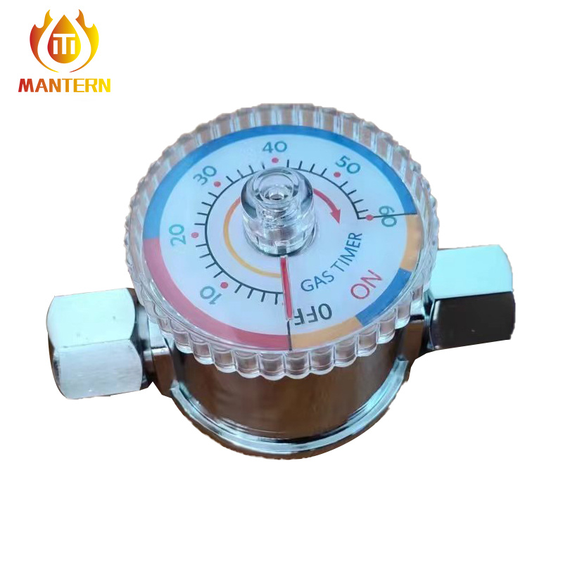
Executing a flawless integration requires patience. The following standard operating procedure outlines the exact mechanical steps necessary to introduce the shut-off device safely into your gas system.
Begin by thoroughly inspecting the newly purchased component under adequate lighting. Peer into the internal chamber to check for manufacturing debris or metal shavings, which can easily clog downstream appliance orifices. High-quality valves typically handle a maximum operating pressure of 0.5 PSI (14 W.C.). Take this moment to verify your measurements one final time. Forcing an incompatible thread will instantly strip the softer brass. The result? A permanently ruined valve and a dangerous leak.
Thread sealant must only be applied to the male threads of the pipe fittings, never to the female threads inside the valve itself. If stray tape enters the internal mechanism, it will jam the 1-hour mechanical gear train. Holding the pipe firmly, use yellow gas-rated Teflon tape to wrap the male threads tightly in a clockwise direction. Apply three full, overlapping wraps. Crucially, leave the very first thread at the tip completely bare to allow for smooth initial engagement.
Identify the directional flow arrow stamped directly into the metal body of the valve. This arrow dictates the strict path the fuel must travel. Thread the main gas supply line into the inlet side. Always hand-tighten the connection first to ensure the threads are seated perfectly. Once hand-tight, apply your dual-wrench method: lock one wrench onto the hex-shaped base of the valve to hold it completely stationary, and use the second wrench to drive the pipe fitting home. Tighten firmly, but avoid brute force that could distort the brass casing.
Next, attach the downstream line leading to your barbecue or fire pit. The specific procedure here varies depending on your regional hardware. If your imported appliance utilizes metric specifications, carefully thread the corresponding flex hose into the 11.5mm gas outlet. Conversely, if you are working with standard NPT fittings, apply your yellow tape to the male adapter and tighten it securely. Pay close attention to the physical resistance as you turn the wrench. If it suddenly binds up after half a turn, stop immediately, back it out, and check for cross-threading.
A heavy brass timer valve should never be left suspended in mid-air, supported solely by the tension of the connecting gas pipes. Over time, vibration will cause the rigid pipe joints to loosen. Securely mount the valve to the structural framing of your masonry block or grill cabinet using stainless steel mounting brackets. Ensure the timer dial is positioned flush against a dry exterior panel, allowing users to operate the mechanism effortlessly.
Once the physical plumbing is complete, your system remains strictly off-limits until a rigorous leak test is performed. Under no circumstances should you ever use an open flame to check for gas leaks. Relying on your sense of smell to detect mercaptan is also insufficient for identifying microscopic breaches.
A simple yet highly effective field solution involves mixing equal parts liquid dish soap and water in a small spray bottle. Slowly turn the main gas supply valve back to the open position to repressurize the system. Leave the newly installed timer valve in the "OFF" position, and do not turn on the appliance burners.
Generously spray the soapy solution over every freshly tightened connection point. Pay particularly close attention to the gas valve outlet size junction and the main inlet junction. Ensure the liquid completely coats the circumference of the threads.
Observe the wet connections closely for three to five continuous minutes. If you witness bubbles actively forming or clustering rapidly around the threads, you have definitively identified a gas leak.
If a leak is detected, shut off the main gas supply immediately. Resist the urge to crank the wrench harder to overtighten the fitting, as this often cracks the valve. Instead, fully disassemble the connection. Use your brass wire brush to aggressively scrub away all the old Teflon tape. Reapply a fresh layer of tape, carefully re-thread the connection, and perform the soapy water test a second time. Proceed only when zero bubbles appear.
Selecting the correct mechanical hardware is just as critical as the installation process itself. The integrity of a high-pressure gas system relies entirely on metallurgical quality. When sourcing a timer valve, prioritize manufacturers that utilize high-grade materials, such as CE/CSA certified solid forged brass or 304 stainless steel internals. These robust materials resist internal corrosion from fuel impurities and withstand harsh outdoor environments.
Furthermore, look for products that provide highly transparent, exact sizing specifications. For commercial applications requiring precise engineering to prevent BTU bottlenecks, you might specifically need a 20mm gas valve to accommodate a metric supply line natively. Evaluating detailed manufacturer technical data sheets directly is the most reliable way to guarantee you secure the exact thread pitch required for your architectural framework.
Proper integration of an automated shut-off device leaves no room for guesswork. A safe, durable installation relies heavily on exact sizing, meticulous preparation, and strict adherence to mechanical protocols. By taking the time to natively match your inlet and outlet dimensions perfectly, you inherently protect your expensive outdoor equipment from pressure drops and safeguard your property against fuel leaks.
Always measure your existing pipe infrastructure with digital calipers before finalizing a purchase. Review your appliance manuals to confirm maximum BTU limits, and invest in a high-quality, certified timer valve that natively matches your system. If you are upgrading your outdoor kitchen and need precision-engineered components, explore the certified range at Mantern to find the exact, safe match for your specific gas infrastructure.
If the sizes do not match naturally, you will be forced to use reducer or expander adapters. While mechanically possible, stacking adapters introduces multiple new thread joints, significantly increasing the risk of gas leaks. Furthermore, stepping down from a larger pipe to a smaller valve inlet creates a permanent flow restriction, which can starve high-BTU appliances of fuel and cause burner performance issues.
Do not rely on standard tape measures or visual estimation. Use a digital caliper to measure the outer diameter (OD) of your male pipe threads. Once you have the precise millimeter or inch measurement, cross-reference it with a standard National Pipe Thread (NPT) or British Standard Pipe (BSP) chart. Remember that pipe thread sizes refer to the internal nominal diameter, meaning a 1/2-inch NPT pipe will actually measure closer to 0.84 inches on the outside threads.
Yes, this configuration is possible but requires a gas-rated brass bell reducer fitting to bridge the size gap. However, you must calculate your appliance's energy demands first. Reducing the pipe diameter immediately at the valve inlet will restrict the total volume of gas. This bottleneck may lower the overall BTU capacity reaching your appliance, potentially resulting in weaker, yellow flames on high-output grills.
A 20mm metric valve is typically utilized in geographic regions that adhere to BSP standards (like Europe or parts of Asia), or it may be specifically required for imported luxury outdoor appliances. To confirm, use your digital caliper to measure the thread pitch and outer diameter. If your existing infrastructure uses standard North American NPT, a metric valve will not seal correctly without specialized, hard-to-find conversion adapters.
While the physical turning of wrenches is straightforward for individuals experienced with advanced home plumbing, working with natural gas carries severe, life-threatening risks. If you lack complete confidence in identifying thread pitches, applying gas-rated sealants correctly, or performing comprehensive pressure leak tests, it is strongly recommended to hire a licensed plumber or certified gas fitter. Professional installation ensures absolute safety and compliance with local insurance regulations.
Yes, directional flow is absolutely critical. Every timer valve features a distinct directional arrow stamped directly onto the metal body. The combustible gas must flow from the supply line into the inlet connection, moving toward the downstream outlet. If the unit is installed backward, the internal spring-loaded mechanical shut-off mechanism will fail to operate properly against the reverse pressure, rendering the safety device useless and potentially causing a total fuel blockage.
Mantern Industrial Co., Ltd. is engaged in international business since 2012. Our aim is to provide good products with competitive price for our clients.
