

Views: 0 Author: Site Editor Publish Time: 2026-08-12 Origin: Site

Identifying the exact source of a fire alarm in complex buildings presents a critical safety gap. Local alarms are frequently insufficient due to high ambient noise, concealed detector placements in HVAC ducts, elevator shafts, or drop ceilings, and the specific needs of hearing-impaired occupants. When a detector triggers in a hidden space, emergency responders and facility managers lose valuable time searching for the source. This delay compromises evacuation protocols and allows hazards to escalate unchecked.
Integrating remote alarm indicators with a Wired Smoke Detector infrastructure solves this problem by providing immediate visual confirmation of a triggered device. This engineering solution bridges the gap between concealed detection and visible notification. By extending the signaling capabilities of hidden sensors to accessible, highly visible locations, facilities maintain strict building code compliance while drastically reducing emergency response times. This guide explores the technical mechanics of connecting remote indicators to wired detection systems, evaluating hardware compatibility, and implementing robust mitigation strategies against common installation failures.
Technical Feasibility: Remote indicators (LEDs, strobes, or annunciators) rely on auxiliary relay bases, dedicated output terminals, or addressable modules built into a commercial-grade wired smoke detector system.
Code Compliance: Integrating remote indicators is often mandated by NFPA 72 (specifically regarding concealed detectors in spaces like drop ceilings or ducts) and ADA accessibility guidelines.
System Compatibility: Successful deployment requires matching the voltage, current draw, and polarity requirements of the remote indicator with the specific output capabilities of a conventional two wire smoke detector or addressable system.
Circuit Supervision: Proper planning of Class A vs. Class B wiring paths, wire gauge selection, and end-of-line (EOL) resistor placement prevents voltage drop and ensures the primary interconnected fire alarm sensor network remains fully supervised and operational.
A successful remote indication deployment provides immediate visual identification of a triggered concealed detector without causing any interference to the primary alarm initiating circuit. The remote device must illuminate reliably the moment the associated detector senses smoke, drawing minimal current to avoid overloading the loop. System integrity relies on this seamless interaction, ensuring that the main control panel receives the alarm signal simultaneously. Field technicians know that a poorly integrated indicator can drag down loop voltage, causing intermittent panel troubles that take hours to trace.
Remote indicators serve specific, high-risk use-case scenarios across modern facilities. Duct smoke detectors represent one of the most common applications. These sensors sit inside HVAC supply and return air ducts, constantly monitoring airflow for smoke particles. Because they are enclosed within sheet metal, a visible wall-mounted or ceiling-mounted indicator is necessary to relay their status to maintenance personnel. Without this visual cue, locating a tripped duct detector in a sprawling commercial complex requires physically opening ceiling tiles and inspecting individual units.
Concealed spaces also demand remote monitoring. Sensors installed above suspended ceilings, under raised floors in data centers, or within locked mechanical rooms remain invisible during routine patrols. Remote LEDs mounted on the adjacent wall or ceiling grid instantly pinpoint the activated device. Furthermore, high-noise or secure environments, such as laboratory spaces or secure server rooms, utilize auxiliary visual signaling to alert occupants who might not hear standard audible alarms over the din of machinery or server racks.
Regulatory frameworks strictly govern these installations. NFPA 72 mandates specific protocols for detectors in concealed locations. Chapter 17 dictates that if a detector's onboard alarm indicator is not readily visible to responding personnel, a remote alarm indicator must be installed in an approved, visible location. This baseline ensures that emergency crews never have to guess which hidden sensor initiated the building-wide evacuation sequence. Compliance inspectors will actively look for these indicators during commissioning, and missing remote LEDs on duct detectors is a frequent cause for failed inspections.
Beyond basic compliance, the architectural integration of these devices requires careful planning. You must consider the viewing angles in long corridors, the ambient light levels that might wash out a standard LED, and the physical routing of the low-voltage wire from the concealed space to the visible mounting location. Proper execution means the difference between a system that guides responders directly to the threat and one that leaves them wandering the halls.
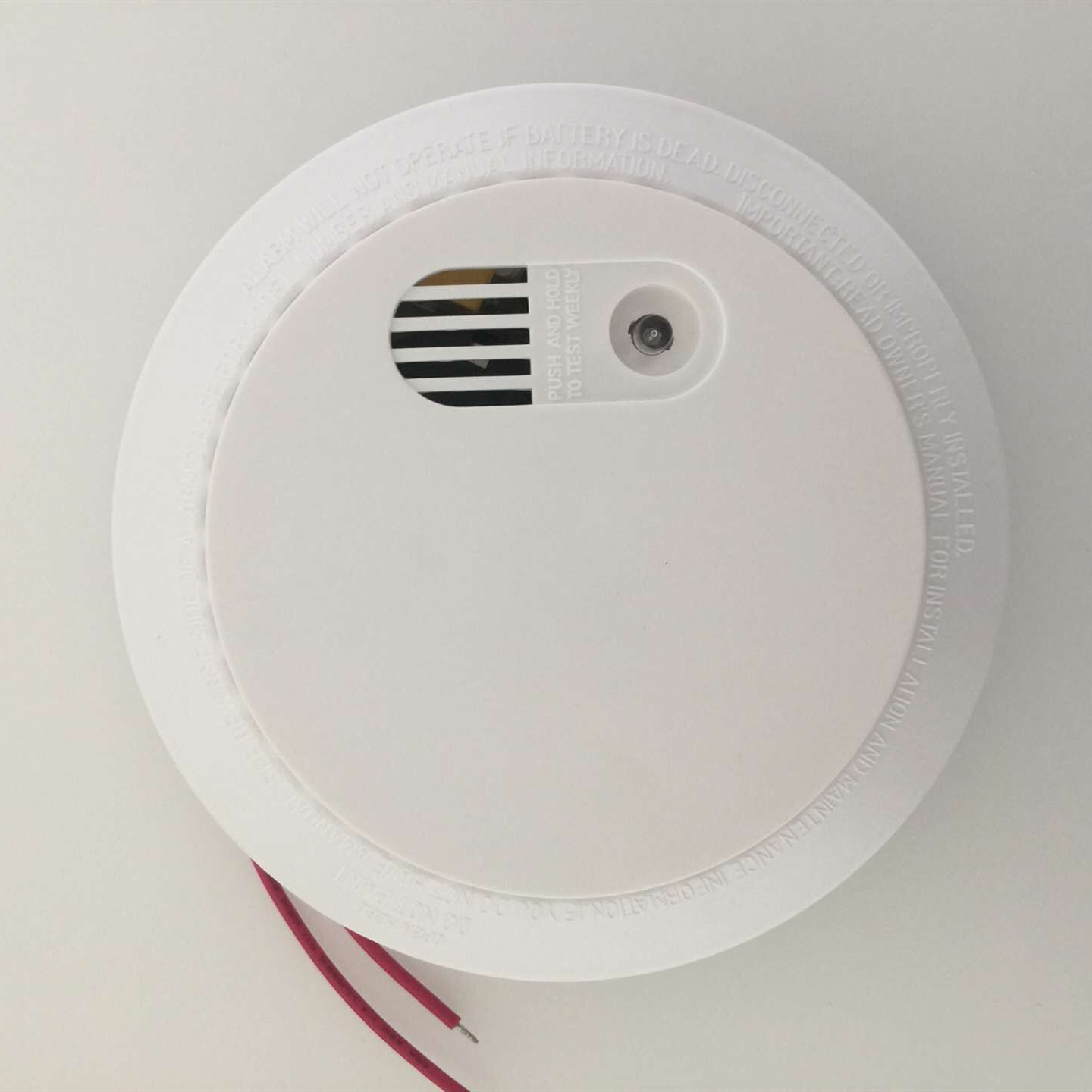
Connecting a detector to a remote indicator requires specific hardware interfaces designed to handle power transfer and signal switching. Specialized mounting bases often provide the necessary physical bridge. These auxiliary bases feature Form A (SPST) or Form C (SPDT) relay contacts. Upon alarm activation, the detector commands the relay to close, switching external power directly to a remote indicator, strobe, or Building Management System (BMS). This isolates the high-current draw of the remote device from the sensitive detection circuit, protecting the panel from unexpected loads.
Integrating a conventional two wire smoke detector involves a distinct wiring architecture. In these systems, power and signaling share the exact same Initiating Device Circuit (IDC). Remote LEDs are driven directly from the detector's designated remote output terminals. The detector utilizes internal current-limiting circuits to ensure the LED receives enough power to illuminate without dropping the loop voltage below the panel's threshold. Installers must pay strict attention to polarity-sensitive wiring connections. Reversing the positive and negative terminals on the remote output will prevent the LED from functioning and can potentially cause a ground fault on the IDC.
To properly wire a conventional remote indicator, technicians typically follow a strict sequence:
Verify the loop is powered down at the main control panel to prevent accidental shorts.
Identify the dedicated remote output terminals on the detector base (often marked as RA+ and RA-).
Run the appropriate gauge wire (usually 18 AWG or 16 AWG) from the base to the remote indicator mounting location.
Terminate the wiring at the remote LED, ensuring strict adherence to polarity markings.
Power the loop and perform a functional test using canned smoke to verify both the detector and the remote indicator activate simultaneously.
The approach shifts when dealing with four-wire or addressable systems. Four-wire systems separate the power and signaling paths. Integration typically uses separate auxiliary power lines, usually 12VDC or 24VDC, alongside the initiating circuits. This setup requires power supervision relays to ensure the auxiliary power remains active. If the power supply fails, the supervision relay drops out, sending a trouble signal to the panel. This guarantees that the remote indicators will actually work when called upon.
Addressable systems take a digital approach. Modern control panels use software programming and addressable control modules to trigger remote annunciators or LEDs. The panel reads the specific electronic address of the activated hardwired smoke detector and commands the corresponding remote indicator to activate via the signaling line circuit. This software-driven logic allows for complex cause-and-effect programming, where a single concealed detector can trigger multiple remote indicators across different zones, or conversely, where multiple detectors in a single concealed space map to one master remote indicator.
Selecting the right detector-indicator combination requires a strict engineering framework. Electrical compatibility stands as the most critical evaluation dimension. Engineers must match the remote LED or strobe operating voltage with the detector’s auxiliary output rating. Most commercial systems operate on 12VDC or 24VDC. Additionally, the current draw (measured in milliamperes) of the remote device must not exceed the maximum output capacity of the detector base. Pulling excessive current will trigger circuit overloads, leading directly to Fire Alarm Control Panel (FACP) trouble conditions or failure to report the alarm.
Visibility, lumens, and candela ratings dictate the physical effectiveness of the indicator. The required luminous intensity depends heavily on ambient lighting and the expected viewing distance. Corridors with bright fluorescent lighting require higher lumen outputs than dimly lit mechanical rooms. When life-safety notification is required, designers must reference ADA standards for visual notification appliances, ensuring the candela rating provides sufficient warning to all occupants. A standard remote LED might pull 10mA and provide basic indication, while a high-candela strobe could pull upwards of 100mA, necessitating external power routing.
Environmental and enclosure ratings determine device longevity. Remote indicators must feature appropriate NEMA or IP ratings tailored to their specific installation environments. Outdoor areas demand weatherproof enclosures to prevent water ingress. Food processing plants require washdown-rated plates capable of withstanding high-pressure cleaning. Hazardous locations, such as chemical storage facilities, mandate explosion-proof housings to prevent the indicator itself from igniting airborne vapors. Installing a standard indoor-rated LED plate in a damp parking garage will lead to rapid corrosion and inevitable failure.
Scalability ensures the system can grow alongside facility expansion. Facility managers must assess how easily additional remote indicators can join an existing loop. Adding devices increases the total current load. Engineers must calculate this cumulative draw to ensure it remains safely below the maximum limits of the initiating circuit. When designing a new wing or retrofitting an existing floor, you must audit the available power budget on the loop before adding dozens of new concealed detectors and their associated remote indicators.
Physical mounting constraints also play a role in evaluation. Remote indicators come in various form factors, from single-gang wall plates to ceiling-mounted octagonal boxes. The chosen hardware must fit the architectural realities of the space. For instance, mounting a remote indicator on a glass partition requires specialized adhesive housings, whereas drywall installations allow for standard recessed backboxes. The physical durability of the faceplate matters in high-traffic areas like gymnasiums or warehouses, where impact-resistant polycarbonate covers prevent accidental damage.
System design requires balancing performance, compliance, and budget. Facility managers and electrical engineers constantly navigate trade-offs when configuring an interconnected fire alarm sensor network with remote indicators. Every design choice impacts installation time, maintenance overhead, and overall system reliability.
The choice between dedicated remote LEDs and horn/strobe combinations presents a primary operational decision. A simple remote LED offers low power draw and wiring simplicity. Its primary function is locating a hidden device. Conversely, a combined horn/strobe unit provides superior notification capability for alerting occupants but demands significantly higher power requirements, often necessitating dedicated power supplies and heavier gauge wiring. You must decide if the goal is simply to guide maintenance staff to a tripped sensor or to actively evacuate the immediate area.
Supervision of the indicator circuit introduces another layer of complexity. Unsupervised remote LED wiring costs less to install and requires fewer components. However, if the wire breaks, the system will not notify the panel, rendering the indicator useless during a fire. Supervised circuits monitor the integrity of the connection between the detector and the remote indicator. While more complex to wire, they provide enhanced reliability and strict code-compliance.
Configuration Type | Primary Advantage | Primary Disadvantage | Best Application |
|---|---|---|---|
Dedicated Remote LED | Low current draw, simple wiring | Visual indication only, no audible alert | Locating concealed detectors in drop ceilings |
Horn/Strobe Combo | High visibility and audible warning | Requires auxiliary power and complex wiring | High-noise environments, ADA compliance |
Unsupervised Circuit | Lower upfront material costs | No panel notification if wiring fails | Non-critical supplementary indication |
Supervised Circuit | Guaranteed integrity, code-compliant | Higher installation and hardware costs | Life-safety critical remote signaling |
Cost of installation versus maintenance efficiency remains a constant debate. Running additional conduit and wiring for remote indicators incurs significant upfront labor and material costs. Yet, this initial investment yields long-term operational savings. Maintenance teams save countless hours by instantly locating a dirty or faulty concealed detector, rather than manually checking dozens of hidden devices. The labor saved during a single annual inspection often offsets the initial cost of the remote indicator hardware.
Finally, engineers must choose between addressable polling and conventional zoning. Addressable modules offer pinpoint accuracy, using software to map remote indicators to specific devices. This simplifies troubleshooting but requires expensive panel hardware. Conventional systems provide cost-effective, zone-based indication, which works well for smaller facilities but lacks the granular diagnostic capabilities of addressable networks. In a conventional setup, a remote indicator might tell you there is a fire above the ceiling in Room 101, but an addressable system will tell you exactly which of the three detectors in that ceiling space has triggered.
Installation and commissioning phases introduce several points of failure that can compromise the entire detection network. Wiring faults and voltage drops represent the most common physical risks. Excessive wire lengths between the detector and the remote indicator cause resistance to build. This voltage drop can prevent the remote indicator from illuminating entirely or, worse, prevent the detector from resetting after an alarm. Mitigation requires precise wire gauge calculations. Engineers must specify 14 AWG or 16 AWG wire based on the exact circuit length, total loop resistance, and the cumulative current load of all connected devices.
Polarity inversion and diode isolation failures frequently occur during rapid installations. Wiring a polarity-sensitive remote LED backward disables the indicator immediately. In some detector bases, this mistake causes a short circuit across the initiating loop, resulting in a constant system trouble signal or a false alarm at the panel. To mitigate this, technicians must enforce strict pre-commissioning continuity and polarity checks using a digital multimeter. Selecting remote indicators equipped with built-in blocking diodes provides an additional layer of hardware protection against reverse wiring.
Overloading the auxiliary power circuit poses a severe risk to system stability. Drawing too much current from a conventional detector base can drop the loop voltage, compromising the primary detection network and preventing other sensors from reporting. Mitigation involves strictly limiting the use of base-powered outputs to low-draw LEDs. For high-draw indicators like strobes or multi-zone remote plates, installers must use external power supplies and isolation relays. Always verify the manufacturer's specification sheet for the maximum allowable current draw on the remote output terminal.
Testing, resetting, and accessibility constraints complicate lifecycle management. Testing remote indicators tied to inaccessible detectors requires specialized hardware. If a technician cannot reach the detector to apply canned smoke, verifying the remote indicator becomes impossible. Mitigation dictates specifying detectors with remote test stations. These stations feature key switches or magnetic test points, allowing maintenance personnel to simulate an alarm condition and reset the detector safely from floor level. This eliminates the need for ladders or lifts during routine inspections.
Ground faults present another significant implementation risk. When pulling wire through metal conduit or across sharp ceiling grid edges, the insulation can strip, causing the copper conductor to touch grounded metal. This creates a ground fault that the main panel will flag. Finding a ground fault on a remote indicator circuit requires isolating sections of the loop and testing for continuity to ground. Using proper wire pulling techniques, installing protective bushings on conduit ends, and utilizing shielded cable in high-interference areas mitigates this risk.
Audit your current FACP capabilities and verify the availability of compatible relay bases or dedicated remote output terminals on your existing detectors before purchasing new hardware.
Calculate the total circuit load and potential voltage drop for all planned remote indicators to ensure your existing initiating device circuits can handle the additional current draw.
Consult with a NICET-certified fire alarm designer to map out all concealed detector locations and ensure the placement of remote indicators complies with NFPA 72 visibility requirements.
Review local AHJ (Authority Having Jurisdiction) requirements to confirm full compliance with any specific regional amendments regarding remote signaling in concealed spaces.
Implement a standardized testing protocol using remote test stations to verify the functionality of both the concealed detectors and their associated remote indicators during annual inspections.
A: Yes, but compatibility depends on the existing hardware. The current detector base must have auxiliary relay contacts or a dedicated remote LED output terminal. You must also verify whether your system is conventional or addressable to select the correct integration method.
A: Maximum distance is dictated by wire gauge, terminal loop resistance, the current draw of the indicator, and allowable voltage drop. You must perform specific calculations based on the manufacturer's installation manuals to determine the exact maximum length for your setup.
A: While they routinely support low-current remote LEDs directly from the base, high-draw strobes usually require a separate Notification Appliance Circuit (NAC) or an external power supply triggered by an auxiliary relay to prevent overloading the initiating circuit.
A: Yes. NFPA 72 requires remote indicators for detectors installed in concealed locations, such as HVAC ducts, plenums, or above suspended ceilings, where the detector's onboard status LED is not readily visible to occupants or responding personnel.
A: Most commercial detectors feature reverse-polarity protection, preventing permanent damage. However, a miswired indicator will fail to light up and can cause a system trouble signal on the FACP. Always verify positive and negative markings during installation.
A: Use remote test stations equipped with key switches or magnetic switches. These devices allow maintenance personnel to simulate an alarm condition electronically, verifying both sensor and remote indicator functionality from a safe, accessible height.
A: A remote LED is a simple, single visual light tied directly to one detector's output terminals. A remote annunciator is a comprehensive zone or addressable panel that displays the status of multiple zones or addressable devices across an entire facility.
Mantern Industrial Co., Ltd. is engaged in international business since 2012. Our aim is to provide good products with competitive price for our clients.
